We define the parts-feeding problem as follows:
The algorithm is given below:
Figures 5,
6, and 7
illustrate how the algorithm proceeds for
a rectangular part. All orientations in map into the single
orientation in
when the frictionless gripper is closed. So
is the image of
, and
is the preimage
of
. Step 3 searches for the widest interval whose
image is smaller
. This interval becomes
.
We can implement step 3 geometrically using a square
box of dimension
. We position the box over the step function
such that the range of output angles contained in the box is smaller than
the range of input angles. That is, the function must enter on the box's
left-hand edge and exit on the box's right-hand edge as illustrated in
Figure 7.
Continuing, wider and wider intervals are found until an interval of width
equal to a period of symmetry in the transfer function is found.
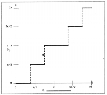
Figure 6: In step 2, the widest single step in the transfer function is identified. All the orientations in (horizontal bar at bottom), map into the single final orientation:
(dot at PI).
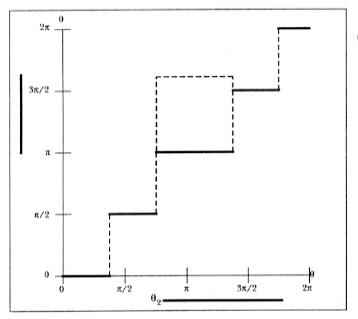
Figure 7: In step 3, we identify the largest interval whose image is smaller than h1 = |THETA1|. This can be visualized by left-aligning a box of dimension h1 with each step. If the squeeze function emerges from the right edge of the box, then the corresponding image is smaller than h1. The largest such interval in this case is THETA2 (shown at bottom).