JawNet
Introduction:Geometric algorithms for design, simulation, and manufacturing are often available only to a small number of researchers and engineers. The rise of Internet makes it possible for public to share resources. Goldberg and his colleges provide FixtureNet, the first fixture design system on the Web. Some other geometric computation software can be found at http://www.geom.umn.edu/.We develop JawNet, an interactive CAD tool to facilitate design of gripper jaws and parts. The JawNet is based upon our self-aligning gripper jaw design algorithms and written in Java. Users can draw parts, define the COM and the friction coefficients, chose the initial and the final orientations; JawNet computes, ranks, and displays the resulting jaw designs. Computer simulation using JawNet can provide users with deeper and more intuitive knowledge of jaw design for manufacturing.
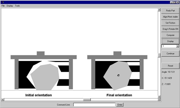
User's ManualIn the left lower corner, there are three numbers: Angle is the degree of part rotational angle from the work-surface; (X, Z) is the location of your cursor.1. Click Define Part, then use your mouse to draw a convex polygon above the black horizontal line (counterclockwise, 10 edges maximum). The polygon represents the part and the horizontal line represents the work-surface; 2. Click Define COM, then use your mouse to move the part's Center of Mass around; 3. Click Align/Next Stable, the part will align with the work-surface in one of its stable orientation. Click the button again, the part will rotate to the next stable orientation; 4. The default value of friction cone half-angles is 10 degree. If you want to change the friction, enter two numbers (degrees of the part-surface and part-jaw friction cone half-angles) into Command Line, then click Set Friction; 5. Click Drag & Rotate OFF, the button changes to Drag & Rotate ON and a gray image of the part in the initial orientation displays, then you can drag the part to rotate it to the desired orientation. Angle shows the rotational angle; 6. Click Compute to run the jaw design algorithm. After a while, an optimal jaw design appears. Black trapezoids represent jaw modules. Move your cursor along the edges of the part and close to a vertex of a jaw module, Angle disappears and the location of this vertex displays; 7. Click Continue to see the computing process of this numerical algorithm step by step; 8. Click Reset or Redo Part to restart.
Note: 1. When Drag & Rotate ON, you can drag and rotate the part; when Drag & Rotate OFF, you can change the part or its COM by dragging its vertices or COM. You can switch Drag & Rotate ON/OFF by clicking the button; 2. Click Display to show the design if the display is incomplete; 3. A number displays above Continue, which is the rank of current
jaw design by total length of linear contact area.
|